

In this tutorial, we will learn how to control a 4×7 Segment Display. To do so, we will use a 4-digit 7 segment display connected to a 74HC595 shift register to simply show whatever integer number from 0 to 9999 we send from the Serial Monitor of the Arduino IDE. If you want to display some numbers, this tutorial is the right one for you.
Parts Required
To build the global setup you must have the following parts:
- ESP8266 NodeMCU v1.0;
- Micro-USB to USB cable;
- 4×7 Segment Display;
- 74HC595N Shift Register;
- 4 x 220 resistor;
- Male to male jumper wires;
- 1 Breadboard;
Note: You do not need to have a NodeMCU board nor an ESP8266 to follow this tutorial. I am using this board because it is very famous and also because I will post future tutorials using wifi communications. In order to use other boards, you just have to change the pin number.
4×7 Segment Display 5641AH
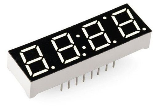
This kind of displays are similar to single 7-segment displays, but with some tricks. To display information such as the time or temperature, you can use this one instead of connecting multiple single-digit displays side by side. If you want to know more about single 7-segment displays, check our tutorial on this topic.
In multi-digit displays, one segment pin (A, B, C, D, E, F, G, and DP) controls the same segments in all the digits, as you can see in figure 2. Multi-digit displays also have separate common pins for each digit. These are the digit pins. You can turn a digit on or off by switching the digit pin. The digit pins (D1 … D4) in our case, are common cathode. So to turn on a digit, pull the pin to GND.
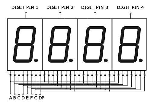
Therefore, we are obligated to write to every digit at the same time. To control each digit individually, we need to use the digit pin (D1… D4) to turn on and off the respective digit. For example, in figure 3 we can see that by pulling to GND the pin D4, we turn on the right digit. Therefore, to write a 4 digit number, like 1230, we have to follow some steps, starting from the right digit:
- Turn off the digits D1, D2, and D3, by pulling them to Vcc;
- Turn on the segments A,B,C,D,E,F, to write the number 0;
- Wait some time;

Now, repeat the step above, but now for the digit D3 until you reach the digit D1.

This is an indication that we need to turn on and off and switch between digits very fast to be able to write something. For those who think that they will see the flickering effect provoked by switching the digits, do not worry because this operation occurs very fast and your eye is not capable of detecting the transitions (Persistence of vision).
Shift Register 74HC595N

A shift register is a circuit you can use to control many outputs (8 here) at the same time while only using a few pins (3 here) of your board. It works on Serial IN Parallel OUT protocol. It receives data serially from the microcontroller and then sends out this data through parallel pins.
Thankfully Arduino provide a helper function specifically for shift registers called shiftOut(), which allows to simply shift the bits in one call.

As you can see in figure 6, pins marked as Q0-Q7 (15 and 1-7) are the output pins. Pin16 is connected to (VCC) 3.3V, whereas pins 8 and 13 are connected to the ground and pin 10 to (VCC) 3.3V. Finally pins 14, 12 and 11 are data, latch and clock pins and are the ones used by NodeMCU to pass data to the shift register.
For further understanding of the logic and function tables of this circuit, you can visit the datasheet, and can also visit an older tutorial on this circuit.
Circuit with Shift Register

Now, let’s go to the fun part! To start, we can connect pins 16 (VCC) and 10 () of the shift register to the NodeMCU 3V3 pin and pins 8 (GND) and 13 (
) to its GND pin.
Then, connect the clock (SRCLK), latch (RCLK) and serial data (SER) pins of the shift register to the NodeMCU digital pins D5, D8 and D7 respectively.
All the parallel data output pins of the shift register (QA – QH) should be connected to the segments of the display (A – DP) by order.
Finally, connect the digit pins to the NodeMCU digital pins D1, D2, D3 and D4. Note that the digit pins need to be connected to current limiting resistors (220Ω) since they are the common terminals of the digits.
In the end, your circuit should be similar to the diagram represented in Figure 8.
Installing Timer Library
In order for us to apply the multiplexing method in our code, it is necessary to install the Timer.h library before we compile it. To do so, we first need to download the library by clicking on the following link:
https://github.com/JChristensen/Timer/archive/master.zip
Then, we need to install it into our Arduino library. Open the Arduino IDE and then select Sketch > Include Library > Add .ZIP Library… and search for the .zip file you have just downloaded, which should be in the Downloads folder (see Figure 9). Once installed, will appear the following message in the Arduino IDE message area: “Library added to your libraries. Check “include library” menu”.

If you want to know more about this library, such as viewing some examples and functions, we suggest you consult this link:
http://www.doctormonk.com/2012/01/arduino-timer-library.html
Coding
As mentioned previously, with this code you can send any integer number from 0 – 9999 through the Arduino IDE serial monitor. To open the serial monitor, you can select Tools > Serial Monitor or simply click on the Serial Monitor button at the top right corner. Then type the number you want to see in the display in the small upper box and click on Send.
Regarding the code, the timer object is used to switch between digits. The segment pins are also turned ON and OFF for each number is stored in a byte array.
In the loop() function, the serial values are read, converted to integers and then to long data types. Then, the values in this long data are separated into single digits in the break_number() function.
Multiplexing is done by the timer class every() function and it calls the display_number() function once every millisecond. This uses the shiftOut() function to send signals to the shift register.
The latch pin is turned LOW before data is sent and turned HIGH afterwards. The function called cathode_high() is used to turn off the screen. Have Fun!
#include "Timer.h" //include timer library
Timer t; // craete a timer object

long number = 0; //declear the variables
int digit_1 = 0;
int digit_2 = 0;
int digit_3 = 0;
int digit_4 = 0;
int timer_event = 0;

int cathode_1 = 5;
int cathode_2 = 4;
int cathode_3 = 0;
int cathode_4 = 2;

int latchPin = 15;
int clockPin = 14;
int dataPin = 13;

int count = 0;
int digits[4] ;
int cathodePins[4] = {5, 4, 0, 2};

byte numbers[10] {B11111100, B01100000, B11011010, B11110010, B01100110, B10110110, B10111110, B11100000, B11111110, B11110110};

void setup() {
  Serial.begin(9600); //serial start and pin config
  pinMode(cathode_1, OUTPUT);
  pinMode(cathode_2, OUTPUT);
  pinMode(cathode_3, OUTPUT);
  pinMode(cathode_4, OUTPUT);
  pinMode(clockPin, OUTPUT);
  pinMode(latchPin, OUTPUT);
  pinMode(dataPin, OUTPUT);
  digitalWrite(cathode_1, HIGH);
  digitalWrite(cathode_2, HIGH);
  digitalWrite(cathode_3, HIGH);
  digitalWrite(cathode_4, HIGH);
  Serial.println("Please enter a number between 0 and 9999");
}

void loop() {
  t.update(); //timer update
  if (Serial.available()) { // read from serial
    t.stop(timer_event); //stop timer if anything to read
    cathode_high(); // blank the screen
    String s = Serial.readString(); //read the serial value
    number = (long)s.toInt(); //convert it to int
    if (number > 9999) { //check if the number is 0-9999
      Serial.println("Invalid number!\nPlease enter a number between 0 and 9999");
      } else {
      break_number(number);
      timer_event = t.every(1, display_number); // start timer again
    }
  }
}

void break_number(long num) { // seperate the input number into 4 single digits

  digit_1 = num / 1000;
  digits[0] = digit_1;
  int dig_1_remove = num - (digit_1 * 1000);
  digit_2 = dig_1_remove / 100;
  digits[1] = digit_2;
  int dig_2_remove = dig_1_remove - (digit_2 * 100);
  digit_3 = dig_2_remove / 10;
  digits[2] = digit_3;
  digit_4 = dig_2_remove - (digit_3 * 10);
  digits[3] = digit_4;
}

void display_number() { //scanning

  cathode_high(); //black screen
  digitalWrite(latchPin, LOW); //put the shift register to read
  shiftOut(dataPin, clockPin, LSBFIRST, numbers[digits[count]]); //send the data
  digitalWrite(cathodePins[count], LOW); //turn on the relevent digit
  digitalWrite(latchPin, HIGH); //put the shift register to write mode
  count++; //count up the digit
  if (count == 4) { // keep the count between 0-3
    count = 0;
  }
}

void cathode_high() { //turn off all 4 digits
  digitalWrite(cathode_1, HIGH);
  digitalWrite(cathode_2, HIGH);
  digitalWrite(cathode_3, HIGH);
  digitalWrite(cathode_4, HIGH);
}
References
https://osoyoo.com/2017/08/08/arduino-lesson-4-digit-7-segment-led-display/#3.2
The 4×7 Display used is 8-pin (5641AH). The link however is to the 6-pin 5641AS (one that I have as well) but not for this.